Mallory Performance ignition systems
- Thread starter campbellju
- Start date
O
Odin
Guest
stumo said:Yes, Rob, that's true also. you might go from 8.5mpg to 8.51mpg
It all helps fella, Better that point one in my pocket than gordon browns :lol: :lol: :lol: :lol: :lol: .
Rob
A
AJ4
Guest
I agree with Rob, just **** around with it until you get something that works. Your always going to get a misfire somewhere, dry air needs a different gap to wet air, rich mixture versus weak mixture at different revs etc etc. Just optimise it for where you want to make all the power and suffer the fact its not going to be perfect everywhere.
Thanks gents. Apparently my Mallory system has left the warehouse. I'll leave the 0.5mm gaps as they are to see if it solves the "engine hot" occasional misfire, problem then try the OE gaps and finally add 0.1-0.2mm on that. Though OE seems the sensible choice, assuming all still okay then a 0.9mm gap sounds enough to me.
I will take Ross's advice and **** around with it, why should the spark plugs be any different
I will take Ross's advice and **** around with it, why should the spark plugs be any different
Last edited:
F
Fusion Ed
Guest
Sorry if this has been said already im on a mobile phone connection and everythging takes ages to load so I have been unable to read all the posts:
This is what you need to do:
The MSD Ignition unit needs a pull-to-ground trigger. This is not mentioned for some daft reason, but you can be sure of this by the mention of connecting to ignition points (if you were to have them) which are always pull to ground.
So in this case we need to find a suitable pull-to-ground trigger that does not upset anything else on the ECU.
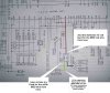
Going from the nissan diagram, the following is what happens:
Pin 36 is the contstant 12v feed to the OEM coil, this will ALWAYS be 12v when the ignition is ON, this wire to the cap (which then goes to ground) can be ignored since you need a direct feed to the ignition module. You could connect the supply to the MSD ignition driver to this but its better to go direct to the battery, or as good as.
The resistor is used as a diagnostic feedback to the ECU from the ignition module. Basically if this resistor is removed etc the ecu will always report an ignition fault.
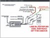
In any case the following will get you going:
Heavy Red to 12v, closer the battery if possible.
Heavy Black to Ground, this must be a good ground
Black to SS blaster coil -
Orange to SS blaster coil +
White to the wire from the lowest wire on the ignition diagram, the one that the resistor connects to, on the coil side not the ecu side of the resistor.
This is what you need to do:
The MSD Ignition unit needs a pull-to-ground trigger. This is not mentioned for some daft reason, but you can be sure of this by the mention of connecting to ignition points (if you were to have them) which are always pull to ground.
So in this case we need to find a suitable pull-to-ground trigger that does not upset anything else on the ECU.
Going from the nissan diagram, the following is what happens:
Pin 36 is the contstant 12v feed to the OEM coil, this will ALWAYS be 12v when the ignition is ON, this wire to the cap (which then goes to ground) can be ignored since you need a direct feed to the ignition module. You could connect the supply to the MSD ignition driver to this but its better to go direct to the battery, or as good as.
The resistor is used as a diagnostic feedback to the ECU from the ignition module. Basically if this resistor is removed etc the ecu will always report an ignition fault.
In any case the following will get you going:
Heavy Red to 12v, closer the battery if possible.
Heavy Black to Ground, this must be a good ground
Black to SS blaster coil -
Orange to SS blaster coil +
White to the wire from the lowest wire on the ignition diagram, the one that the resistor connects to, on the coil side not the ecu side of the resistor.
F
Fusion Ed
Guest
as for coil gaps I would say keep to manufactureres stock recommendations, if the spark is strong enough dont open it up any more.
Get your head round this lot then :shock: :lol: :lol: :lol:
http://www.sr20forum.com/archive/index.php/t-104438.html
It makes my average posts look like play school. Its confirmed my plan though, start at the 0.5mm for a bench mark. Go to stock and then increase up to 1.0mm gap. ****ing around with it as Ross might say. :-D In the article, someone using a 400hp SR20DET found 1.0mm worked well on a track.
With a good amp/coil, the big gap seems to help off boost performance whilst still enabling high boost ignition. At high boost, the performance would be similar past a stock gap from what this article is saying. Nissan will have chosen the stock gap as a compromise between the on/off boost loads and the cost of the ignition system to spark across the gap.
.....oh and the service life of the individaul bits as Stu correctly pointed out
Last edited:
T
tro||
Guest
WARNING.campbellju said:
anything posted by bigtoe on the sr20forum will be to much for some simple folk, so if you feel you fit that description you're probably best off not reading it as your head may implode.
bigtoe=kickarse
Interesting readingcampbellju said:Get your head round this lot then :shock: :lol: :lol: :lol:
http://www.sr20forum.com/archive/index.php/t-104438.html
It makes my average posts look like play school. Its confirmed my plan though, start at the 0.5mm for a bench mark. Go to stock and then increase up to 1.0mm gap. ****ing around with it as Ross might say. :-D In the article, someone using a 400hp SR20DET found 1.0mm worked well on a track.
With a good amp/coil, the big gap seems to help off boost performance whilst still enabling high boost ignition. At high boost, the performance would be similar past a stock gap from what this article is saying. Nissan will have chosen the stock gap as a compromise between the on/off boost loads and the cost of the ignition system to spark across the gap.
.....oh and the service life of the individaul bits as Stu correctly pointed out
Just in case someone buys the MSD unit 2nd hand without instructions, heres a copy from the MSD website
http://www.msdignition.com/pdf/6%20series/6series.pdf
See how similar it is to the Mallory one posted by Jim ealier in this thread.
Anyway, using a combination of Ed's suggestion and the MSD install booklet, I will be installing the MSD ingnition box as below attachments
Attachments
-
 111.6 KB Views: 41
 -
 113.6 KB Views: 55
stumo
Active Member
Steve, yes that's the place to splice the white MSD wire into the circuit.
I don't think it matters if you splice before or after the resistor as the (MSD) white wire is only a trigger for the unit.
The MSD gets it's power from the main (heavier duty) pos and neg wires.
I've never checked the voltage in the MSD white wire but looking at the sparks produced when earthing it out (to check out the system) it's probibly around 12V.
Last edited:
What is, where Ed suggests or where I suggest ??stumo said:Steve, yes that's the place to splice the white MSD wire into the circuit.
I was/am going to take the feed (for the white MSD wire) from the point the green/yellow wire plugs into the coil as it would be so much easier for me as I don't have a OE coil plug, just a female spde connector and I can't see it's going to make alot of difference at what point it's spliced into that section of wire, as long as it's before the resistor (not after it, on the ECU side).stumo said:I don't think it matters if you splice before or after the resistor as the (MSD) white wire is only a trigger for the unit.
The MSD gets it's power from the main (heavier duty) pos and neg wires.
I've never checked the voltage in the MSD white wire but looking at the sparks produced when earthing it out (to check out the system) it's probibly around 12V.
(i'm prob going to talk out my **** but...) would the (probibly) 12V cause any problems attaching it to the green/yellow wire?
If it will, i guess adding a diode would sort it out but with the .7volt drop would that bring the check light on?
i'll get me coat *shuts door*
Steve.
Steve, I thought the discssion for the G/y was the output of the amp or the input of the coil. The resistor does create a potential divider circuit and switches the feed voltage from 12V down to 9V at the coil. Whether its for an error code too I couldn't say, I use a PFC nowadays ;-) If Ed thinks it does matter then take it from the coil which is what I thought he was saying :?
Either way, I can't see the MSD unit caring whether it gets 9V or 12V on its input. I bet inside the MSD box it gets reduced down to 5V or less to trigger another power transistor anyway. These electronics designers don't often say 12V is okay but 9V will turn your box into a big black smoking pile of bits.
Its like something off Macgyver now, just go for it and cut the blue wire :doh: :lol: :lol: :lol:
Like a scene from Macgyver or not.................... :lol: :lol:
Apart from the fact I just want to get this right the first time I fit it and not just f**k about untill it works. :?
I thought that one of the ideas of this thread/forum/club was to all help one another. Don't get me wrong you have all been very helpful but a part , all be it a small part, of the reason I'm asking all these questions and confirmation is so that when other people buy similar, weather MSD or Mallory or................. then they have a cystal clear image of what we have done and how these systems are fitted.
Steve
P.S. Cheers for all the help (and patience ;-) )
stumo
Active Member
Everything will be confirmed when you pull your finger out and fit it, if it works then it's confirmed that what we've been discussing was correct!:-DI thought that one of the ideas of this thread/forum/club was to all help one another. Don't get me wrong you have all been very helpful but a part , all be it a small part, of the reason I'm asking all these questions and confirmation
A
AJ4
Guest
Dont hold your breath Steve, I tried for weeks to find out how to wire up the 2 WIRES on the PFC boost control kit, I assume I was the first person ever in the world to actually do it as no-one else could tell me
What you really want is someone to go, " oh its easy, I fitted mine like this, and it all works fine". Unless your also the first person in the world to do something as well
I'll post a message on one of the 'alternate' forums as I'm sure a few people use them already
What you really want is someone to go, " oh its easy, I fitted mine like this, and it all works fine". Unless your also the first person in the world to do something as well
I'll post a message on one of the 'alternate' forums as I'm sure a few people use them already
Last edited by a moderator:
A
AJ4
Guest
Steve, call http://www.the-garage.co.uk/ on 01698-375789 and ask for Marc, he's just fitted Rishi's MSD and knows how it all goes
Do you mean I wasn't the first person in the world to do that :doh: :lol: . 2 wires, totally not obvious which way round to put them. I'm still not sure whether it was good planning or just the 50/50 chance of getting it right but it worked.AJ4 said:Dont hold your breath Steve, I tried for weeks to find out how to wire up the 2 WIRES on the PFC boost control kit, I assume I was the first person ever in the world to actually do it as no-one else could tell me
Steve, TBH, I thought similar in that by me going through this process with you I'll be able to plug mine straight in. I was only joking, I always get the mcgyver feeling whenever I cut a wire. Blue, blue, blue........ or was it red?
Use the G/Y at the coil for your 9V trigger to the MSD unit. "IF" that doesn't work then you can still cut the G/Y at the amp out to give a 12V trigger to the MSD, that will also eliminate your resistor as well. I can't see the MSD driver caring which signal it takes as I bet both are above the threshold it needs.
Follow Ross's links or at worst wait a week and I'll have mine in.
Rishi
Still waiting on some shims!
AJ4 said:Steve, call http://www.the-garage.co.uk/ on 01698-375789 and ask for Marc, he's just fitted Rishi's MSD and knows how it all goes
Thats will be fitting mine as he used the same system on Jav's MR2 2.2L T88
Rishi