Mallory Performance ignition systems

campbellju

Moderators
Staff member
Looking at the service manual, white is the trigger for the OE "amp", Black goes to earth and green/yellow goes to the coil. On your coil you should have Black/Red too back to earth through a capacitor. The Green/yellow also splits off and goes to your Ballast resistor and for some of the mallory coils it advises you leave this in. For your MSD system, it might use its own ballast resistor? No idea.

By having the MSD wires to the coil from the unit, you are eliminating the OE capacitor.

The brief manual advises using the "amplifier output" so my "guess" would be to use the G/Y wire from the OE amp to your white wire of the MSD and eliminate the OE ballast resistor. I would want to trace a few wires and do the odd internet search before I conformed it though.
 

campbellju

Moderators
Staff member
Technically you were right stu as the white wire is still the "trigger" to the power transistor. The MSD asks for the amp out though
 

stevepudney

GTiROC CHAIRMAN
Staff member
Stu, isn't that basically what I suggested in the above post. Look at the Nissan wiring diag, you can see the wire that goes from the power transistor to the coil.

Wouldn't that make my MSD wiring Diag correct ?? Anyone ??

Jim, the MSD instructions also has the same diag as that and I was wondering about it but the one I posted above just seems to make more sense.

Thoughts

Steve
 

Attachments

Last edited:

stumo

Active Member
Steve, yeah, i only saw your post after i posted so i deleted it.(i'm still at work (unlike some:roll: )and i do actually do work, contrary to opinion)
 

campbellju

Moderators
Staff member
:focus: :lol: :lol:

I'm not sure what else to say Steve. The "power amplifier" is a big transitor and basically an electronic switch. The white wire is the equivalent of the trigger to the relay. The green/yellow wire is the "output" of this relay as the other wire goes to ground.

If you look at the trouble shooting bit for the SR20DET ignition system in Section 1 you can see what I'm looking at for wire colours.

The diagrams you've shown for the MSD make it look like you don't need a ballast resistor so tap into a wire at the amp. Whether white or G/Y, both are essentially supplying the trigger but at different voltages.

You might find the MSD can take a 5-14V input and it actually doesn't matter.
Ross will come along now and tell me I have forgotten all my univesity training again :doh: :lol:
 

stevepudney

GTiROC CHAIRMAN
Staff member
So just to confirm :roll:

by connecting the white wire of the MSD unit to the Green/Yellow wire that exits the OE power transistor and enters the OE coil is what I'm suggesting, then the red "needing a switched 12 volts" wire of the MSD unit to the Red/Black coil wire, which looks to me to be a live feed from the ignition switch.

As diagrams below

Thoughts again :-D
 

Attachments

campbellju

Moderators
Staff member
HI Steve, I'm actually here with Stu. We both agreed you need the white wire of the MSD unit to the green/yellow at the exit of the Amp, not at the coil. We think the switched 12V just means your ignition switch like you show. However, if you cut it at the coil, you will still include your capacitor in the circuit. This might be right or wrong again but TBH I don't think 2.2uF will make a massive difference
 

stevepudney

GTiROC CHAIRMAN
Staff member
Just to be a pain in the ****, whats the purpose of the resistor between the Power Transistor and the coil on the OE wiring ?

If I take the feed for the MSD (white wire) after the resistor will the feed be cleaner/weaker/stronger ?? ............You say 2.2uF won't make a massive difference, so I guess the feed will be slightly weaker ?? but I can't help thinking the OE resistor is there for a reason and if a feed is taken from the G/Y wire at the amp output the resistor will be redundent, or does it have another purpose other than the feed to the coil ??

Steve
 

campbellju

Moderators
Staff member
It creates a potential divider circuit so the coil sees less than 12V (10V? can't remember off hand) for normal running. At startup the ECU switches out the divider circuit so all 12V go to the coil to make sure it is still saturated with current whilst the starter motor is taking a load of current too. I tried removing it to over saturate the OE coil at normal running but with a scope saw no real difference in primary coil current. This means the standard coil is perfectly matched to the driver at 10V (?) Its a bit like an overboost cicuit at startup. I think some classic systems worked the other way to give the starter motor more power at startup.

If your coil is 12V then you don't want any potential divider cicuit. Stu says he doesn't run one on his jeep and that hasn't gone bang yet. By fitting the MSD system, my impression is you get rid of the overboost facility and install a 7L viper engine instead.

The capacitor acts like a damper in the circuit and stops resonating noise feeding back through the coil. My guess is the MSD system will have one built in and even if it does, the small OE capacitor won't make a noticable difference to operation.
 

stevepudney

GTiROC CHAIRMAN
Staff member
Cheers Jim & Stu for the help :-D

I'll give it a go later, fingers crossed

Jim what coil will you be using with the Mallory ignition ?

Steve
 

campbellju

Moderators
Staff member
A mallory coil ;-) Links to both on the first page.

I still can't find a good answer to plug gaps. Will report back if I can find anything.
 

stumo

Active Member
Plug gaps should be as big as you can get away with without any missfire.

If you're running .5 at the moment with the standard system i'd be surprised if you couldn't increase that quite a bit with the MSD/Mallory systems.
 

campbellju

Moderators
Staff member
Thanks Stu.

What I'm thinking is the plug gap defines the resistance and also the voltage. bigger gap = bigger voltage but bigger pressure also equals bigger air electical resistance and also bigger voltage. for exmaple, a 0.5mm gap on a 1.8 bar charge is similar in elctrical resistance to a 0.7mm gap on a 1.0 Bar charge. The numbers are wrong but you can see where I'm going. The ultimate limit would be the 55KV from the coil which might be 40KV at the plug and 1.2mm at 1.8 Bar. Here is my query, the MSD system might fire happily at 40KV across the plug giving huge sparks but will it cause your plugs to overheat or reduce their life to a few thousand miles. The air and mix charge may only need the amount of energy supplied at 15KV so everything else is overkill.

The way I see it, the normal advantage of longer discharge time through a wider gap is completely negated by the MSD's CD system

All just ideas really.
 

stevepudney

GTiROC CHAIRMAN
Staff member
My plugs (Denso IK 27's) are set at the standard 0.7mm as they were supplied. As this is the gap I get the misfires then my theory is that the MSD system will bridge that gap quite happily and my misfire problems will be solved.....maybe :roll:

With a little luck

Steve
 

stumo

Active Member
Jim, you're right, the higher boost pressure means a bigger air resistance, the higher the voltage needs to be to jump the gap.

The wider plug gap helps in igniting more of the mixture (ie a simple explination might be a longer(in length) spark has a larger "surface area" in contact with the mixture)

All the Ampage does is give a "fatter" spark, which again, helps ignite more of the mixture.

The longer discharge time (or the multi sparks at lower revs) helps getting all the mixture to fire.

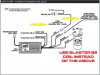
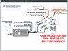
Having seen the lightning storm produced by my MSD setup i can't see it not helping you guys at high boost pressures.
 
Last edited:
O

Odin

Guest
From what I've read in the past the bigger the gap the better fuel economy you will get and a smoother power delivery also, I think it will just be a case of trial and error until you find the biggest gap that doesn't give you a misfire .


Rob
 
Top